
Introducing MEMS and I2C
The first digital microphone I picked up is a Knowles SPH0645LM4H-B on a board - I didn't fancy trying to solder one just yet. The MEMS part of the microphone looks to be very similar to electret - a flexible diaphragm and a rigid backplate making up a capacitor. As the diaphragm moves relative to the backplate, the capacitance changes. If the capacitor has a charge on it, you can see the voltage change as the capacitance changes. Knowles has a handy design guide if you want to know more about the parts inside. From the design guide, we can see that the inside looks like the following: This MEMS microphone is connected to an ASIC which has a whole bunch of things on board to allow us to receive information from the microphone itself. For all MEMS microphones (as far as I can find), there's a charge pump and an amplifier. This is pretty much in common with many different microphones. That's all that's needed for it to be an analog microphone. But, this is a digital microphone, so there's more to take the analog signal and make it digital. Taking a closer look at the datasheet for the SPH0645 shows us there's a whole bunch of components to make the magic happen.


The script accepts a wave filename as input and, crops the audio to the first eight seconds, and then draws the amplitude and spectrum graphs. I found that the data from the microphone had a DC component to it, so I utilized scipy's detrend() function in order to remove the DC offset. Not doing this means the spectrum output would have a huge DC spike that would swamp the rest of the signal.


We start with an analog MEMS microphone, with the requisite charge pump (red) and amplifier(yellow). This generates an analog signal, which is then fed into a one-bit sigma-delta (ΣΔ) converter (green). The ΣΔ converter generates a series of pulses, the density of these pulses representing the input on the ADC - it's one bit remember! The converter outputs a pulse density modulation (PDM) bitstream. You can read more about Sigma-Delta converters at Analog.com. The output of the converter is then fed into a decimator (orange). This simultaneously reduces the data rate (as we're decimating it), at the same time as increasing the bit depth. In this particular microphone, it takes 64 bits and decimates/filters them. The combination of decimation and low pass filter (turquoise) converts the PDM signal into PCM and reduces the high-frequency noise present. Cheshire Engineering have a good page on using decimation and FIR filters to convert PDM into a multi-bit PCM signal. Lastly, the tri-state control means that two microphones can share the same I2S bus, alternating which one is outputting its signal in time with the WS signal.
Interfacing the microphone
I'm using an ESP32, as it has a couple of built-in I2S interfaces. This makes it much easier to work with, as trying to do this with SPI brings challenges of synchronizing the bit clock and LR clock (WS) together. The ESP32 has an IO matrix so that peripherals can be connected to different pins, as we see fit. In my case, I'm using the following pins:
| GPIO | Mic | Purpose |
| 14 | BCLK | Bit clock |
| 12 | WS/ LRCLK | Left/Right control |
| 32 | DOUT | Data output |
| 3.3v | 3.3v | Power |
| GND | GND | Ground |
If you're wondering, WS stands for Word Sync although it's sometimes also called LRCLK - they're both the same thing here. You can probably guess it's designed to select left or right channel audio.
You'd be forgiven for imagining that I2S was standardized and that you can just plug two devices together. It isn't quite that simple. There seem to be some variants and the biggest difference seems to be timings around when WS changes vs data becoming valid. Looking at the ESP32 technical reference manual, it becomes apparent that there are three supported I2S modes. A picture is probably the best way to illustrate the differences in timing.

The Phillips and MSB look similar, except there's a clock cycle between WS changing state, and that state becoming valid with the Phillips implementation. The SPH0645LM4H-B looks to utilize the Phillips I2S mode. That means if you select the MSB mode on the ESP32, the timing differences mean the MSB from the microphone slips to become the LSB on the other channel! That's half our dynamic range gone, disappearing into distortion. Fortunately, there is a fairly easy fix for this - setting the I2S_RX_MSB_SHIFT bit in the I2S_CONF_REG and setting the I2S_RX_SD_IN_DELAY bit in the I2S_TIMING_REG. I have to admit I'm not sure exactly what the I2S_RX_SD_IN_DELAY bit actually does - it's not clear from the documentation.
Once I had half an idea about how to set the I2S port up, I borrowed some code from others who had done this so I could get something up and streaming samples over the serial port. I noted that although the microphone specifies 18 bits of resolution, it outputs 32 bits of data. Remembering that the decimation/filter needs 64 clock cycles to do its work and that I2S transmits two channels of audio, you can see that 32*2 gets the 64clock cycles needed. Putting the interface into 24bit mode would just mean the decimation/filter block only gets 48 clock cycles, and you don't get sensible audio from it! We get 32 bits words of data from the microphone, with 18 bits of right justified audio in it. As the audio is in the form of signed words, we don't need to do anything clever as it's already in a highly usable form.
Getting sensible data
While I've included some of the code I used in this post, you can find all the code at https://github.com/GrahamM/ESP32_I2S_Microphone if you're curious or if you want to reproduce this.
While a serial port is a great tool while figuring out how things work, it's not really a suitable speed for working with audio! It did, however, allow me to figure out what I was doing when grabbing data from the I2S interface. That's a great start. The next step was to stream it across something a bit faster than the serial port. That means WiFi, and to ensure there's no retransmission, I also utilized UDP to send the data.
As a quick check, I could utilize VLC to play the audio received via the UDP stream. It took me a couple of attempts to get the right command line, but this should work. Getting the wrong fourcc means you get headphones full of static!
vlc.exe --demux=rawaud --rawaud-channels 1 --rawaud-fourcc s32l --rawaud-samplerate 16000 udp://@:3333
Now that I could record data on something with a bit more storage than the ESP32, I wanted to look into a few things. I'd noted from the datasheet that there were limits to the clock speed. As the clock speed directly sets the sampling rate, I wanted to know if the microphone really only worked at speeds indicated between 2048kHz and 4096kHz. Those correspond to 32kHz and 64kHz sampling rates - it takes 64 transitions on the clock line to get one sample so we just divide by 64 to get the sample rate. I suspected I could probably go slower, as datasheet indicates the microphone doesn't power down until the clock drops below 900kHz - that would be equivalent to just over 14kHz sampling rate. We can test this by running different sampling rates on the ESP32.
I'd also wondered if there was any connection between sampling rate and the background noise the microphone generates internally. All microphones generate noise, and this particular one indicated it had a signal to noise ratio of 65dB(A). My assumption had been that the noise level would probably increase with the sampling rate. We can test this by placing the microphone somewhere quiet, and seeing what it picks up. Quiet in this case was early in the morning, inside a glasses case with lots of foam padding inside, and away from local noise sources. I still had to avoid the occasional vehicle that drove past though.
Lastly, I'd wondered if I could run the microphone fast enough, would it pick up ultrasound? This needed something that could generate ultrasound. I had a spare ultrasound transducer that runs at 40kHz lying around, and I could drive that with a signal generator.
All of these wonderings needed some kind of analysis to be performed. Capturing an audio sample, and then looking at the amplitude of the noise and performing a fast Fourier transform to get the frequency view seemed to be a good way to do this. With the UDP transmitter, I just needed a simple python script to capture samples from UDP and write them out to a wave file with an appropriate header. It's not going to win awards for beauty, but it got the job done.
By manually adjusting the sample rate in the ESP32 code, and then telling the receive script the sample rate, I can create wave files that are readable by other tools. Now I had wave files, I needed a tool to do some level of analysis. I already knew I wanted amplitude and spectrum, so I spent some time familiarising myself with matplotlib and scipy so that I could generate suitable output graphs. This meant fixing the axes so that I could do a direct comparison between graphs - otherwise having to handle changing scales makes things more challenging! The resultant script looks like this:
Analysis
The graphs that show the amplitude and spectrum analysis are all at the end of this post as there are eleven of them. The sampling rates I covered were mostly all multiples of 16kHz and were:
- 16kHz (1024kHz clock)
- 32kHz (2048kHz clock)
- 44kHz (2816kHz clock)
- 48kHz (3072kHz clock)
- 96kHz (6144kHz clock)
- 112kHz (7168kHz clock)
- 128kHz (8192kHz clock)
- 144kHz (9216kHz clock)
- 160kHz (10240kHz clock)
- 176kHz (11264kHz clock)
- 192kHz (12288kHz clock)
Sample rates
Is the microphone limited to working from 32kHz up to 64kHz? Actually no - it seems to work quite well at other sampling rates that are outside the specifications. 16kHz works just fine, as do higher rates. However, there is a twist once you go above 112kHz sample rate.
Noise levels
I noted that as I worked up from 16kHz up to 112kHz, the spectrum of the noise floor seems to get lower. I'm wondering if this means there's a certain amount of noise energy, and it just gets spread over a larger and larger spectrum, making it less apparent. This would suggest that sampling at 112kHz would result in less noise, but I'm not sure how to actually quantify this.
Once you get to 128kHz, there's a huge jump in the noise. Both 128kHz and 144kHz seem to have similar amounts of noise across the spectrum, although the amplitude seems very different. I'm wondering if this means that the decimation/filtering blocks are now unable to keep up and that I'm getting a signal that's not correctly scaled. One way of testing this would be to sample a constant signal at 112kHz, and then switch to 128kHz to see if the signal also gets correspondingly louder too.
Moving up to 160kHz and above, there's another big jump in the noise level. This makes me wonder - am I actually seeing a change in microphone, or am I just seeing that the ESP32 is rounding my sampling rates as it's clock dividers can't produce the requested sampling speed? I couldn't find any relatively straightforward way of identifying the actual clock frequency set - so this would require an oscilloscope or frequency counter to measure. However, the amplitude seems very different between 144kHz and 160kHz, so I feel relatively confident that these two were definitely using different clocks.
Ultrasound
On being able to hear ultrasound, I don't have any calibrated sources, so I was only able to use what I had to hand. Using a 40kHz ultrasound transducer, and a signal generator set to produce a 40kHz sine wave with relatively low amplitude (500mV), I was able to see the signal turn up on the spectrum view.

As the transducer is tightly coupled to its design frequency, I wasn't able to utilize it at other frequencies. Instead, I grabbed a small speaker designed to operate as the earpiece on a cell phone and hoped that it could produce output higher than 20kHz. Setting the signal generator to 50kHz, I tried again. Although it was a long shot, I seem to have had some success. The signal generator has a 50-ohm output impedance, and the speaker has 30-ohm coil, so they're not well matched.

I think that's a pretty positive response for being able to hear ultrasound. It would have been good to generate some kind of response graph, but I don't have the equipment for that.
Noise/Spectrum graphs
16kHz sample rate

32kHz sample rate

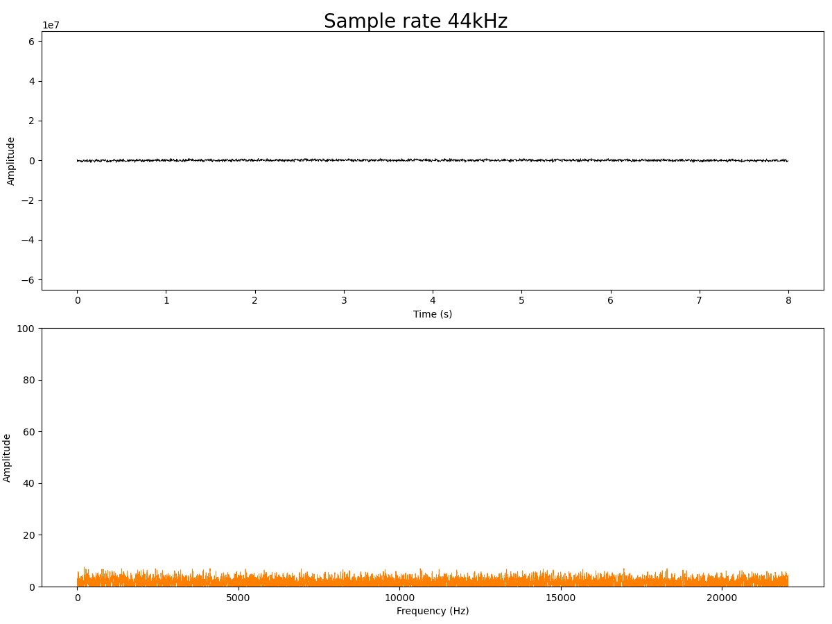
44kHz sample rate
48kHz sample rate

96kHz sample rate

112kHz sample rate

128kHz sample rate

144kHz sample rate

160kHz sample rate

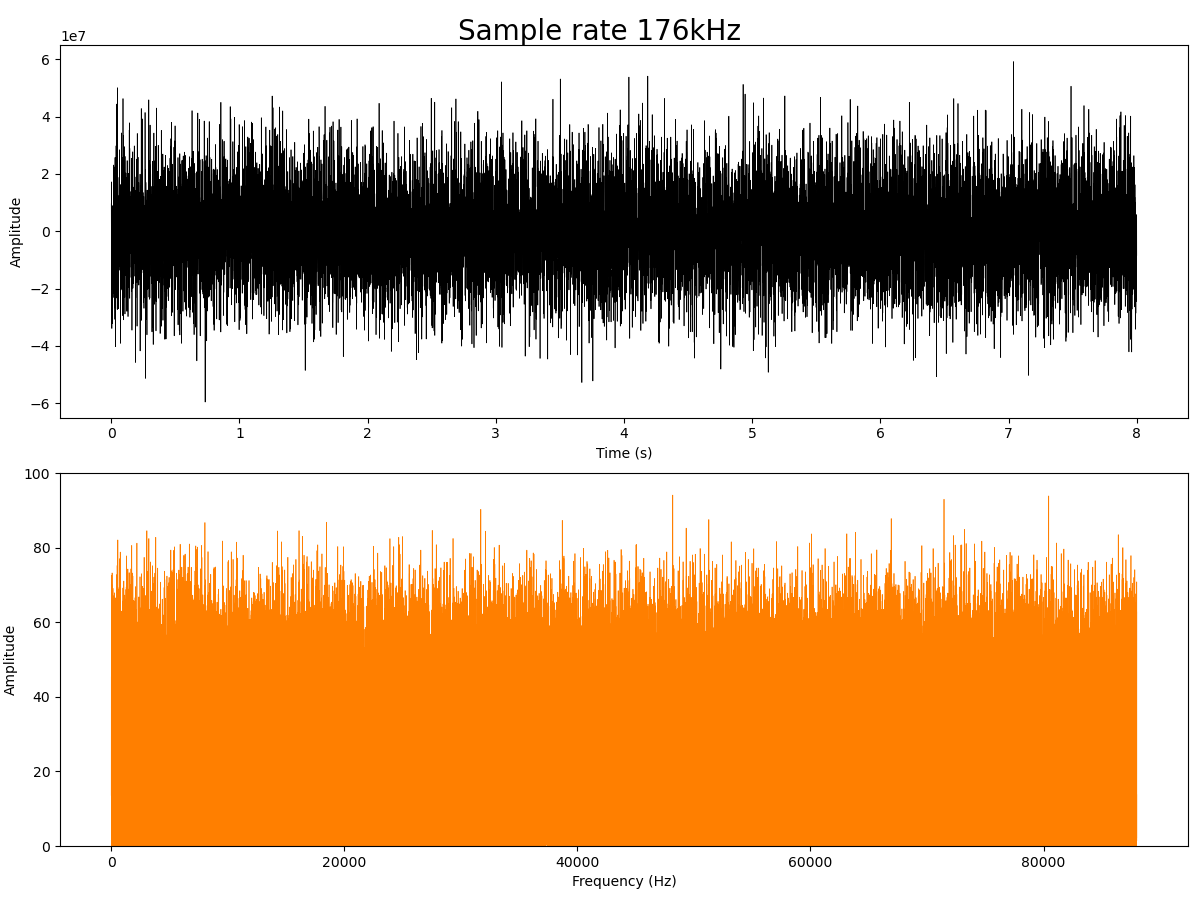
176kHz sample rate
192kHz sample rate

Hello!
ReplyDeleteI need to record animal voices in the range of about 10 kHz to 80 kHz.
At the output, you need a wav file for hardware analysis. Not for listening.
Could you tell us in more detail what board you used, is it possible to get a high-quality recording at 192 kHz or the noise level will not allow it?